[src: http://www.electro-tech-online.com/attachments/clock_mits-gif.6102/]
Simple PLC Flasher
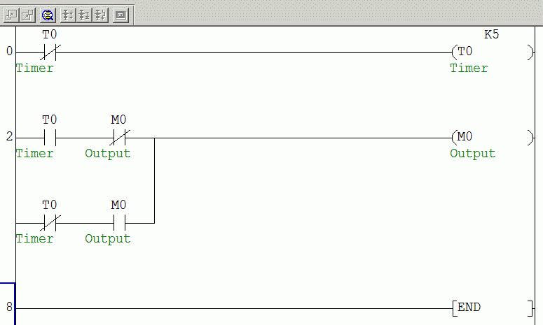
This is a very simple ladder diagram that flashes the "Output". The "Output" is turned off for a period of time then turned on for a period of time and the sequence is repeated.
The "Init" contact is initially zero and by putting it normally closed it will enable the on delay timer "T1" which determines the flashing off time. When "T1" set value is counted, the contact "T1" will be turned on and the "Output" will be also turned on.
When the "Output" is on, the on delay timer "T2" which determines the flashing on time will be enabled and so "T2" contact will be on which results in turning "Init" contact on.
When "Init" is on, timer "T1" will be off because "Init" which enables it is normally closed. When "T1" is off the "Output" will be off and so timer "T2" will be off and "T2" contact will be off which results in turning "Init" contact off.
When "Init" contact is off the sequence is repeated as timer "T1" will be enabled then the "Output" after "T1" counts .. and so on.
Using only one timer:
Here the flasher is done using only one on delay timer, but both on and off times are the same.
Initially "Init" is off so by putting it normally closed it will enable the on delay timer "T1" and after counting to its set value "T1" will turn on "Init".
With "Init" on and the contact "Output" off the coil "Output" will be on.
In the next scan cycle "Init" is on from the first cycle so the normally closed "Init" will be off and the timer "T1" will be deactivated and the coil "Init" will be off.
From the previous scan the "Output" was on so the normally closed contact "Output" will be disconnected and the normally open contact "Output" will be on.
With "Init" off and "Output" contact on the coil "Output" will be energized.
In the next scan cycle "Init" is off so it will enable "T1" and hence "Init" coil will be energized.
With "Init" on the "Output" coil will be off and all starting conditions are returned so the sequence is repeated.
[source: http://misrautomation.blogspot.com/2010/01/simple-plc-flasher.html]
Flasher
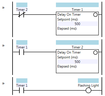
This Ladder Logic Programming Pattern stumps most novices, especially if they don’t really “get” ladder logic. How do you make a light flash on and off once per second?Here is the two-timer variant of the Flasher pattern:

Flasher – Two Timer Variant
Here’s how it works: initially both timers are off, and their elapsed time values are set to zero. Timer 1 starts timing immediately. After 500 ms, Timer 1 is done timing and its output contact (sometimes called “done bit”) turns on. When this happens, Timer 2 starts timing, and the Flashing Light coil turns on as well. After another 500 ms, Timer 2 is done timing and its output contact turns on. On the next scan, this causes the rung input condition to Timer 1 to turn off, which immediately resets Timer 1, which means Timer 1’s output contact also turns off, resetting Timer 2 on the same scan and also turning off the Flashing Light coil. Now both timers are off, so on the next program scan Timer 1 will start timing again and the cycle repeats. Here’s an example timing diagram:

Some things to note: the Flashing Light turns on during the second half of the cycle (i.e. it starts off for 500 ms and then turns on for 500 ms). If you want the Flashing Light coil to be on initially, change the Timer 1 contact in the third rung from normally open (N.O.) to normally closed (N.C.).
Timer 2’s output contact only stays on for one program scan. That means it acts like a one-shot or a pulse. Program scan times can vary widely in PLCs. Older PLCs with slow processors and long ladder logic programs can have scan times in the hundreds of milliseconds. Newer PLCs have typical scan times in the tens of milliseconds, and PC-based PLCs like Beckhoff’s TwinCAT might have scan times in the sub-millisecond range. This is important because it affects the repeatability and accuracy of your timers. If your PLC has a 250 ms scan time then the period of the Flashing Light coil in the above example will vary anywhere from 1000 ms to 1500 ms. That’s because each timer is going to vary from 500 to 750 ms. If the program scan time is 10 ms, then the Flashing Light coil’s period will range from 1000 ms to 1020 ms (which is much more reasonable).
If you need your timers to be more accurate than this, then you’ll have to dig into the documentation of your PLC. You may be able to create a “high speed task” that runs more often than the main program. Typically this higher speed task would be driven by a timer interrupt which preempts the main logic.
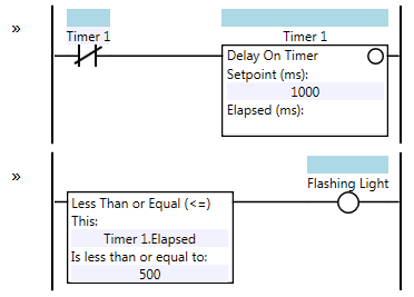
The two-timer variant of the Flasher pattern shown above isn’t the only way to do this. There is a one-timer variant that is just as simple to understand, and has the advantage of being a little shorter:

Flasher – One Timer Variant
Note that the Flashing Light coil will initially be on, and will turn off when Timer 1’s elapsed value exceeds 500 ms. You can reverse this by changing the Less Than or Equal instruction to a Greater Than instruction. Here’s a timing diagram of the one-timer variant:

This one-timer variant reduces the inaccuracy of the timer from two scan times to one. For instance, if your PLC has a scan time of 250 ms, the one-timer variant’s Flashing Light coil will have a period ranging from 1000 ms to 1250 ms. That’s significantly better than the two-timer variant.
Also note that the self-resetting timer pattern (Timer 1 resets itself and then immediately starts timing again) is actually creating a one-scan pulse every one second. This is a pattern in itself that you may see used for other purposes.
[source: http://www.contactandcoil.com/patterns-of-ladder-logic-programming/flasher/]